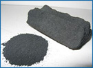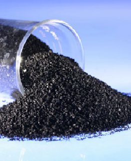
Granular Activated Carbon (GAC):
premium virgin activated carbons made from high quality bituminous coal, coconut shell and anthracite coal raw materials for liquid and vapor phase applications.
We offer high quality virgin-carbons for liquid and vapor phase applications. Some of the applications we specialize in include:
Liquid phase:
– Removal of trace organic contaminants
– Pesticide removal
– MTBE removal
– Disinfection by-product (DBP) removal
– Drinking water treatment
– Industrial process water treatment
– High purity water applications
– Home water filtration systems
Vapor phase:
– Chemical process applications
– VOC control from air strippers, soil vapor extraction and air sparge systems
– Control of tank vent emissions
– HVAC
– Odor control
– Solvent recovery of low boiling point solvents
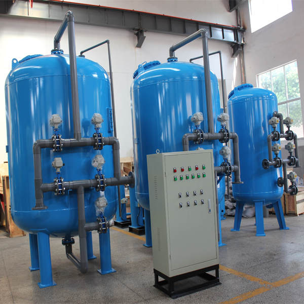
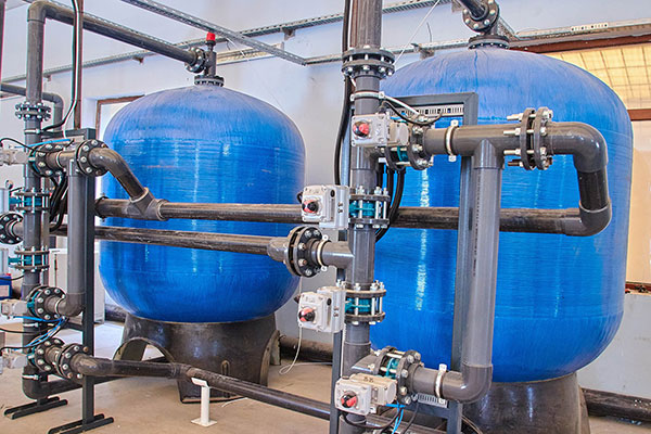
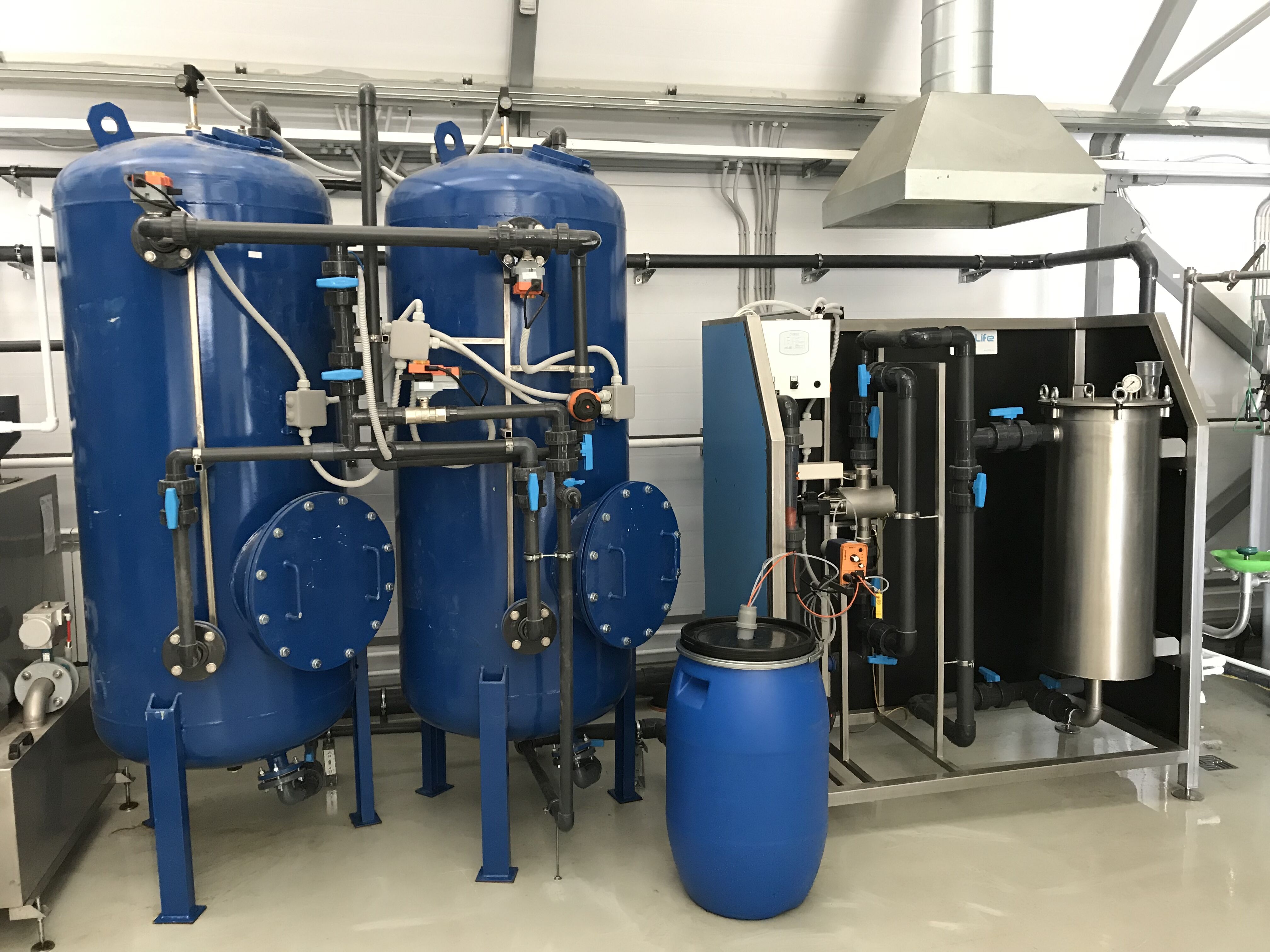
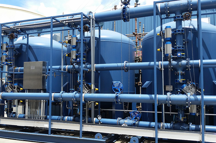
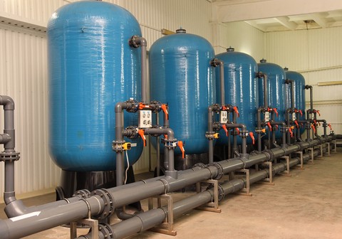
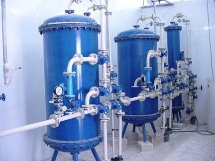
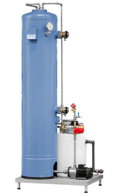
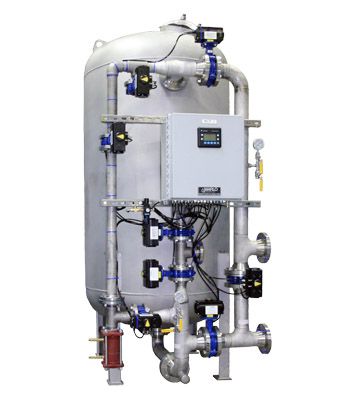
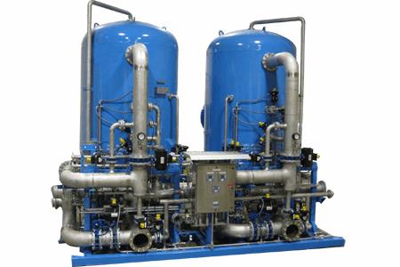
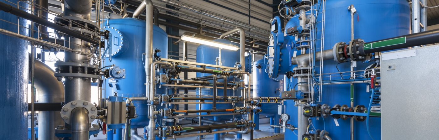
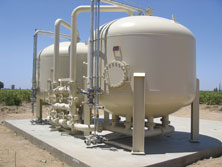
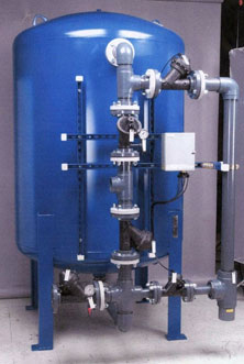
Liquid Phase Carbon Treatment Equipment and Systems:
Water Technologies provides activated carbon adsorbers and systems to filter and remove contaminants from liquid streams for industrial, municipal or commercial applications. Our systems are permanent, hard-piped as well as options for removable adsorber equipment.
UnitedMas Technologies offers liquid phase adsorber equipment and systems for the treatment of various treatment applications, including:
– Decolorization
– Process water filtration
– Groundwater remediation
– Wastewater filtration
– Tank rinse water treatment
– Pilot testing
– Underground storage tank clean up
– Leachate treatment
– Dechlorination
– Spill cleanup
– Food grade
– Drinking water
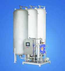
Vapor Phase Carbon Treatment Equipment and Systems:
activated carbon adsorbers and systems to treat malodorous, VOC and other industrial plant emission problems.
Our systems are permanent, hard-piped as well as options for removable adsorber equipment.
– API separator vents
– VOC control from soil vapor extraction (SVE) systems and air strippers
– Wastewater and product storage tank vents
– Process vents
– Refinery and chemical plant wastewater sewer vents
– Laboratory hood exhausts
– Soil vapor extraction (SVE) remediation system off-gases
– Controling emissions from waste processing oprations (i.e., tank cleaning)
– Backup VOC control device for thermal oxidizers
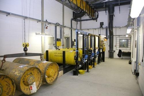
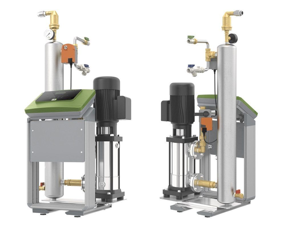
Hot Water Sanitization for Activated Carbon Adsorbers:
Hot-water sanitation effectively protects against detrimental bacterial growth in the activated carbon bed, thereby limiting carbon replacement costs and the associated system downtime.
Many industries such as pharmaceutical, food and beverage are turning to, chemical-free, hot-water sanitization to meet product quality requirements and save time and resources. Hot-water sanitization effectively protects against detrimental bacterial growth in the activated carbon media bed, thereby limiting carbon replacement costs and the associated system downtime.
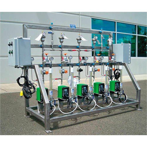
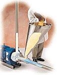
Powdered Activated Carbon (PAC) media, Equipment and Systems:
powdered activated carbons have been specifically developed for the removal of a broad range of organic contaminants from potable, waste and process waters.
Powdered activated carbon (PAC) has a relatively smaller particle size when compared to granular activated carbons and consequently, presents a large surface to volume ratio.
As such, PAC is not commonly used in a dedicated adsorber vessel, due to the high headloss that would occur. Instead, PAC is generally added directly to other process units, such as raw water intakes, rapid mix basins, clarifiers, and gravity filters.
Applications for powdered activated carbon include:
– Dechlorination/chloramine reduction
– Removal of organic contaminants
– Taste and odor reduction
– Disinfection-by-product (DBP) removal
– Pesticide removal
– Landfill leachate
– Drinking water treatment
– Groundwater remediation
– Wastewater treatment
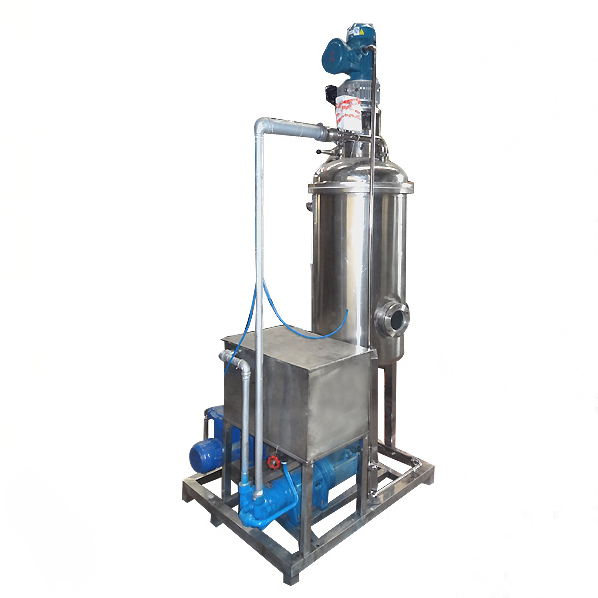
Solid Liquid Seperation :

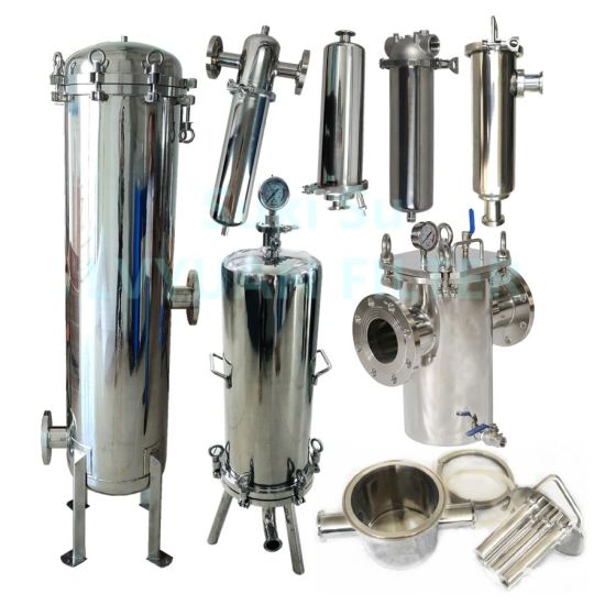
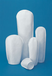
Bag Filters and Accessories:
Suspended solids and other fine particles can be removed from liquid streams by passing them through filters.
Bag filters are a convenient and economical choice for applications that require gross particulate removal. Particulates are trapped in the bag for quick disposal. Bag filters are available for low flow and come in welded or sewn styles. They have multiple micron removal efficiencies
Housings for bag filters are stainless steel and polypropylene.
We are the industry leader in providing components and cartridge filters, including replacement cartridges for filters that are manufactured by other vendors.
Cartridge Filters and Accessories:
Depending upon the application and water treatment requirements, filtration systems use a variety of media to remove contaminants.
We provide a wide range of media, from sand, anthracite and quartz to conditioned media for iron and manganese removal, activated carbon, and replacements for membranes and cartridge filters. Our filtration systems include cartridge, gravity, greensand, walnut shell, fine sand and multimedia.
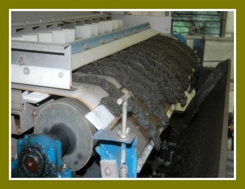
Cloth Type Filter Systems:
Woven polyester pleated panel design disc filters increase treatment capacity and is an ultimate barrier for suspended solids in tertiary treatment processes. The inside-out filtration design allows for a higher operating headloss capability, ensuring a more sustainable operation in terms of more throughput, better feed distribution, and fewer backwash frequencies. Applications include; water reuse, tertiary filtration and process water filtration.
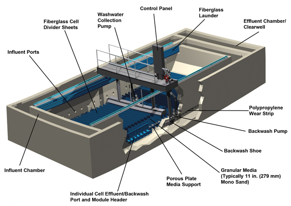
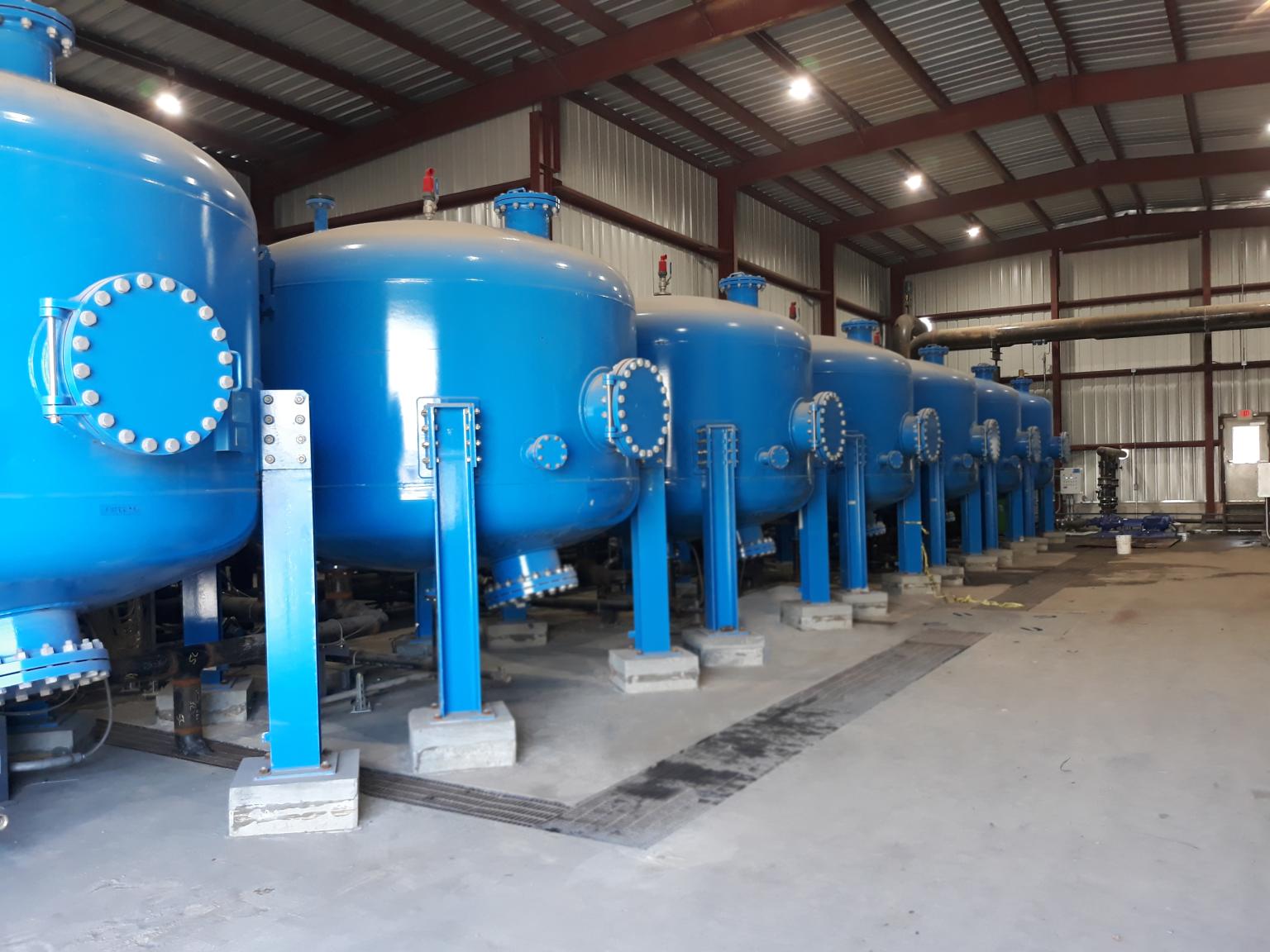
Granular Media Filter Systems – Gravity Type:
Filtration technology, from simple media filters to advanced membranes, is central to municipal and industrial water treatment systems. Interest in these technologies will grow in the future as shrinking water supplies and rising water costs put pressure on the market. Suspended solids and other fine particles can be removed from liquid streams by passing them through filters.
Filtration, typically used as a “polishing” step, refers to the capture of particles by passing water over or through one or more media. Filtration is the key to producing high-quality effluents required for modern regulatory compliance or reuse.
Filtration system technologies used in modern advanced treatment are mostly well established. Changes in the marketplace are steadily moving these new methods from specialty applications to the mainstream. Two trends are largely responsible, reduced water supplies and stricter regulations.
We design and install water and wastewater gravity filters of all kinds–shallow bed, traveling bridge, deep bed, packed filters, pressure filters, precoat filters and more, which use a variety of filtration media including sand, gravel, activated carbon, and other granular media.
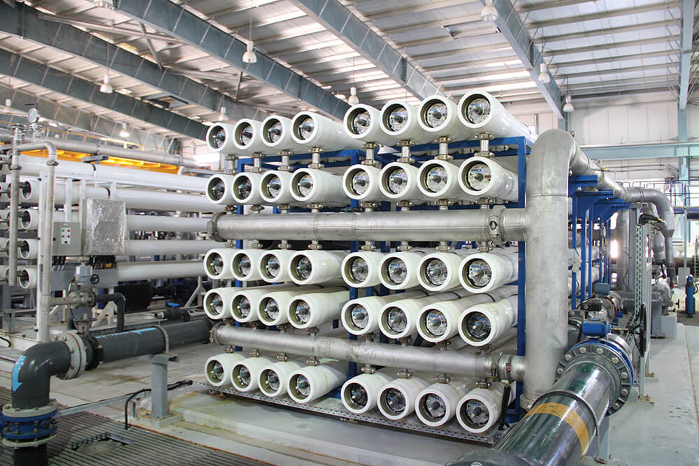
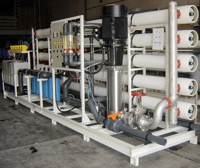
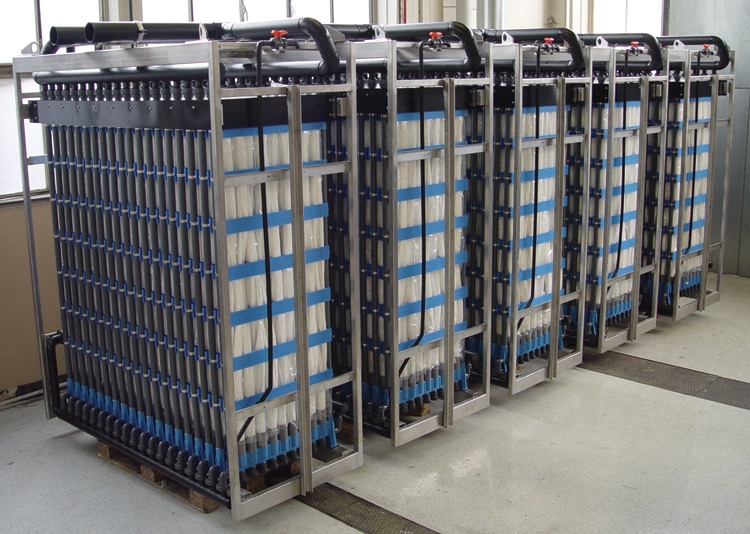
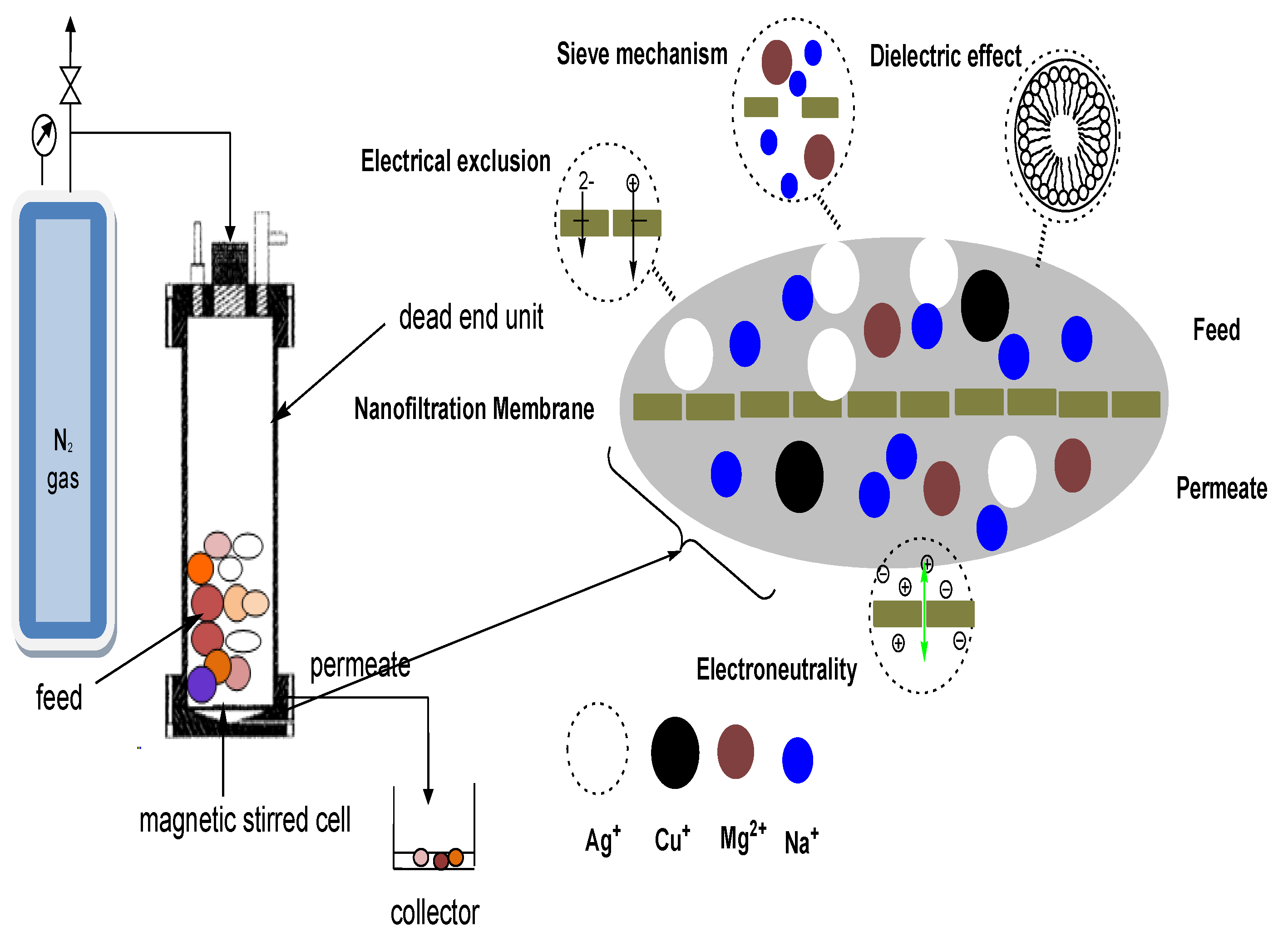
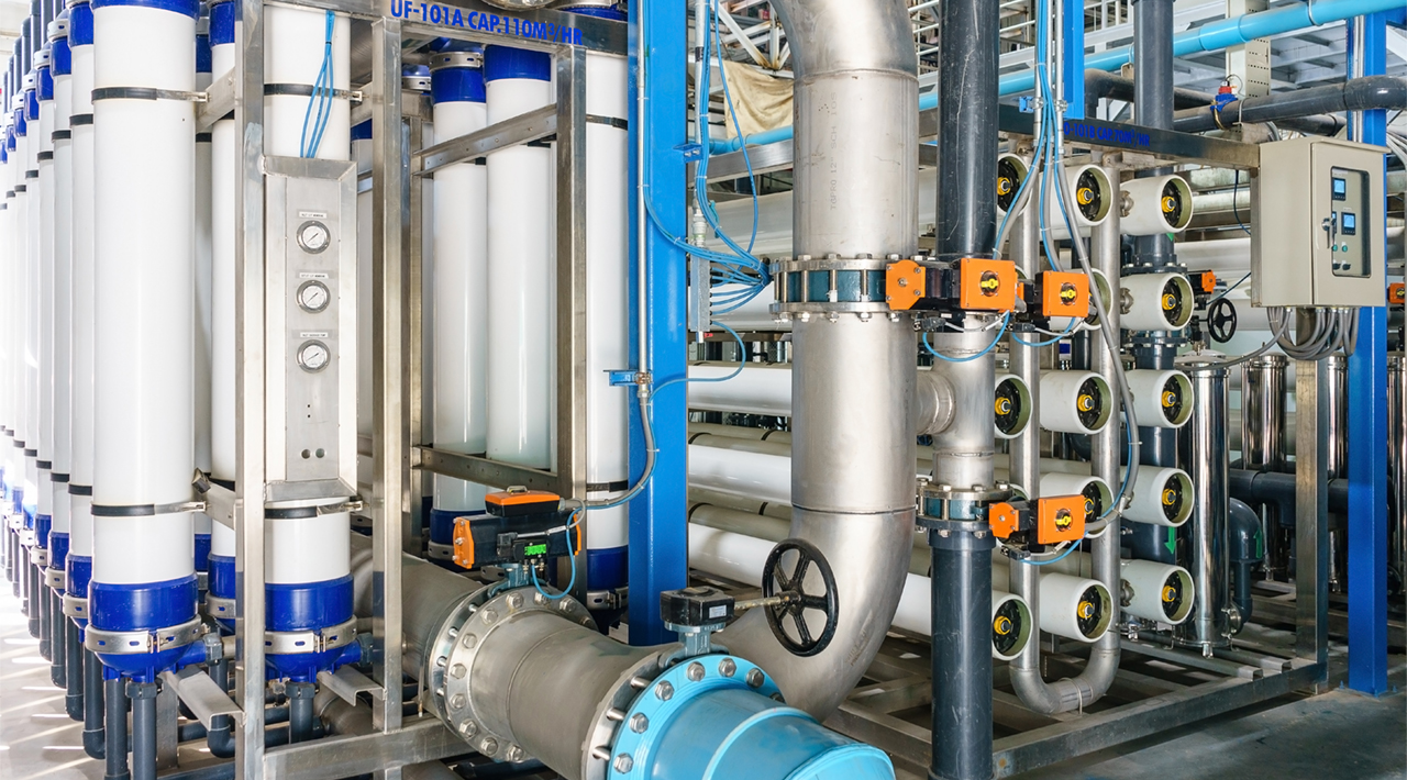
Our membrane filtration systems accomplish microfiltration, ultrafiltration, nanofiltration, and reverse osmosis.
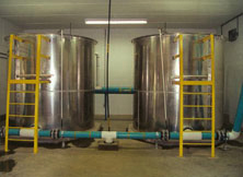
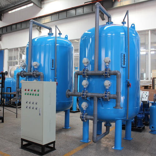
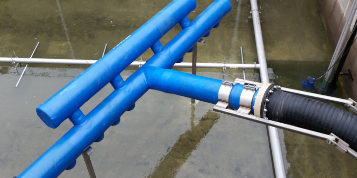
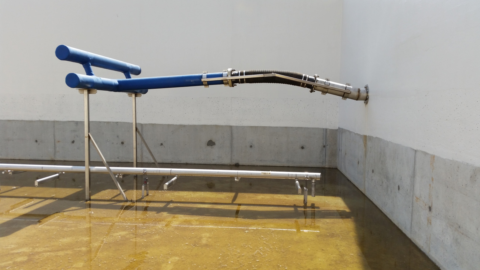
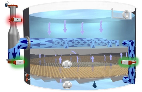
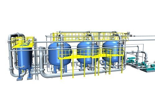
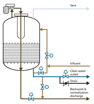
Gravity Filter Systems:
Suspended solids and other fine particles can be removed from liquid streams by passing them through gravity filters.
We design and install gravity filters of all kinds–shallow bed, traveling bridge, deep bed, packed filters, pressure filters, precoat filters and more, which use a variety of filtration media including sand, gravel, activated carbon, and other granular media.
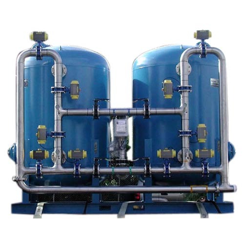
Media – GFH, Greensand, Walnut Shell & Specialty:
Depending upon the application and water treatment requirements, filtration systems use a variety of media to remove contaminants.

We provide a wide range of media, from sand, anthracite and quartz to conditioned media for iron and manganese removal, activated carbon, and replacements for membranes and cartridge filters. Our filtration systems include cartridge, gravity, greensand, walnut shell, fine sand and multimedia.
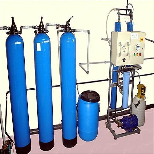
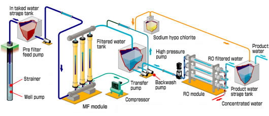
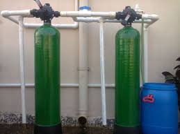
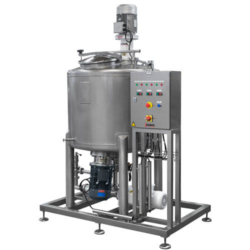
Packaged Water Treatment Plants:
Packaged drinking water treatment plants are safe, reliable and cost effective, specifically geared for the needs of small communities. We know it is sometimes difficult to comply with current and future regulations. That’s why we have developed packaged water treatment systems that take the guesswork out of solving your contaminated drinking water problems.

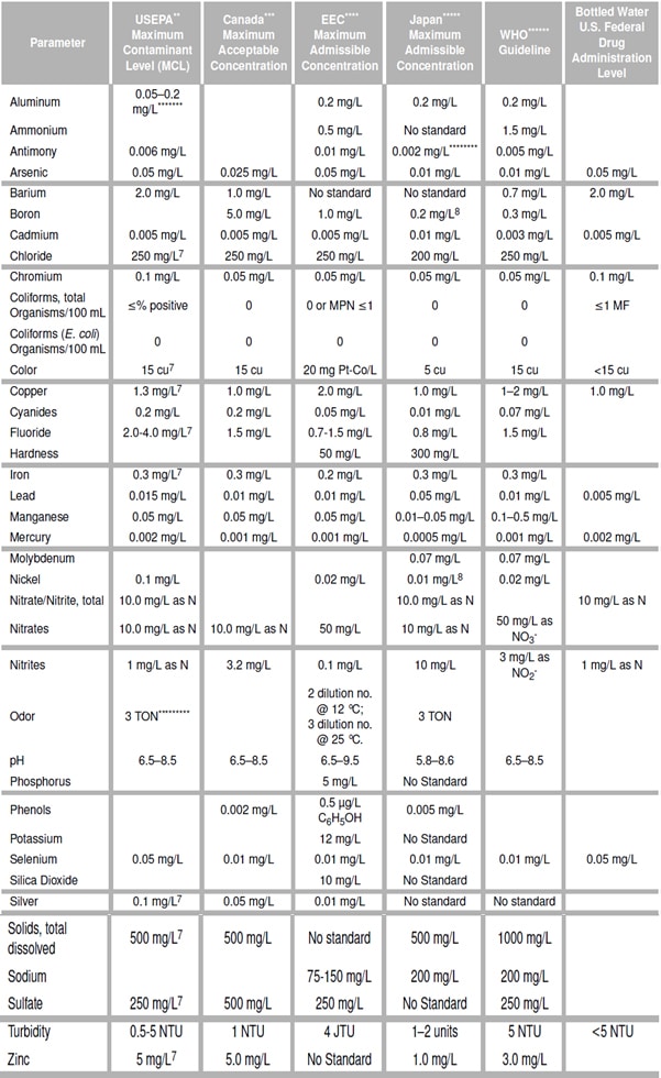
The right package treatment technology for your water needs is dependent on a number
of factors, including raw water source, flowrate and effluent requirements. In order to determine what type of water treatment technology accurately suits your situation, it is important that you first analyze the quality of your incoming water supply. This ensures the water treatment equipment you purchase will meet your specific water quality needs. If you need help to determine your water analysis, we can assist in analyzing and reporting on your water sample.
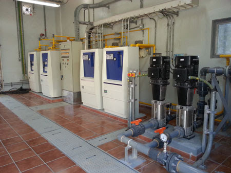
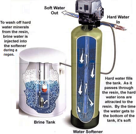
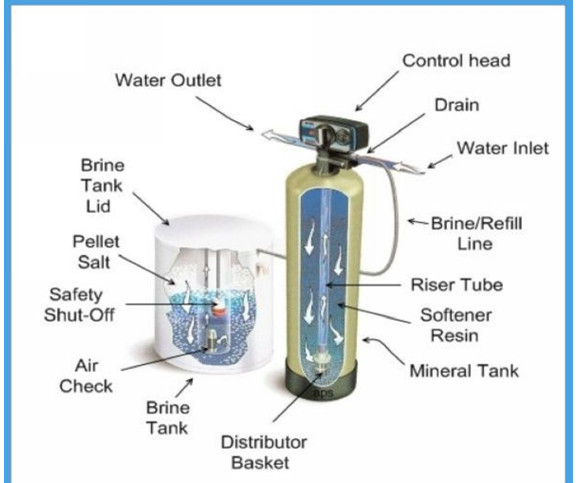
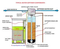
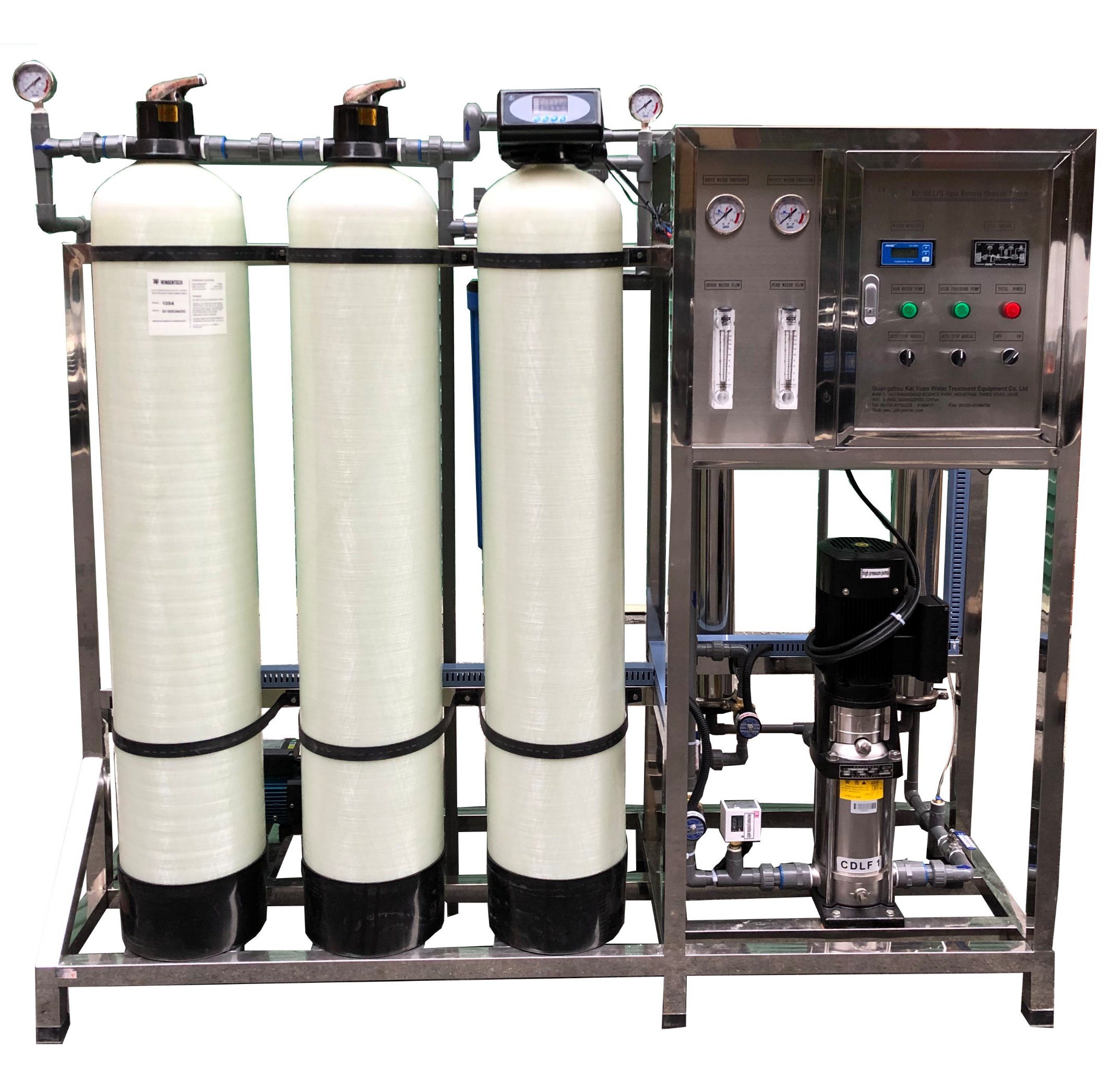
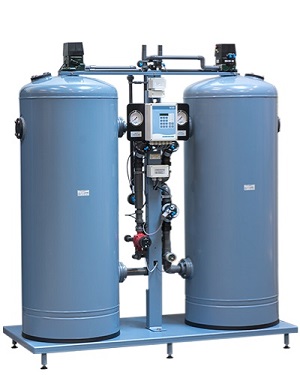
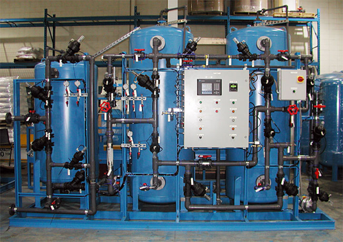
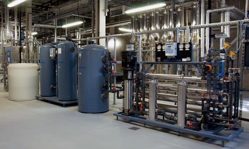
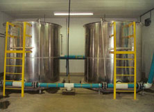
Deionizer/ Demineralizer/ Dealkalyzer Products:
Deionization is the use of ion exchange to remove ionic substances from a solution. Ion exchange is a chemical process that uses ion exchange resin to attract dissolved contaminants, leaving pure water.
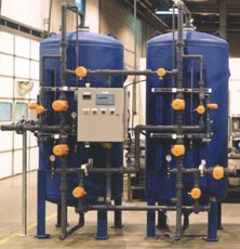
We offer complete systems to produce pure water for rinsing, boiler feed or any other application where our quality engineered and manufactured deionizers will produce the quantity and quality of water needed for your application.
Mixed Bed Deionizers: Commercial and Light to Medium Industrial Applications – When you need higher quality water with a more neutral pH than separate bed systems, as well as enhanced silica and CO2 removal, mixed bed deionizers are the appropriate deionization systems to use.
Two Bed Deionizers: Commercial and Light to Medium Industrial Applications – An acid regenerated cation vessel piped in series with a caustic regenerated anion vessel enables our two bed deionizers to provide high-quality water over the length of the service cycle.
Packed Bed Deionizers: Industrial Applications – Using ion exchange membranes, resins and electricity, our packed bed system produces water of high purity. These chemical-free systems are especially suited for utility in general, pharmaceutical and microelectronics industries.
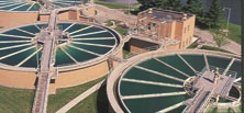
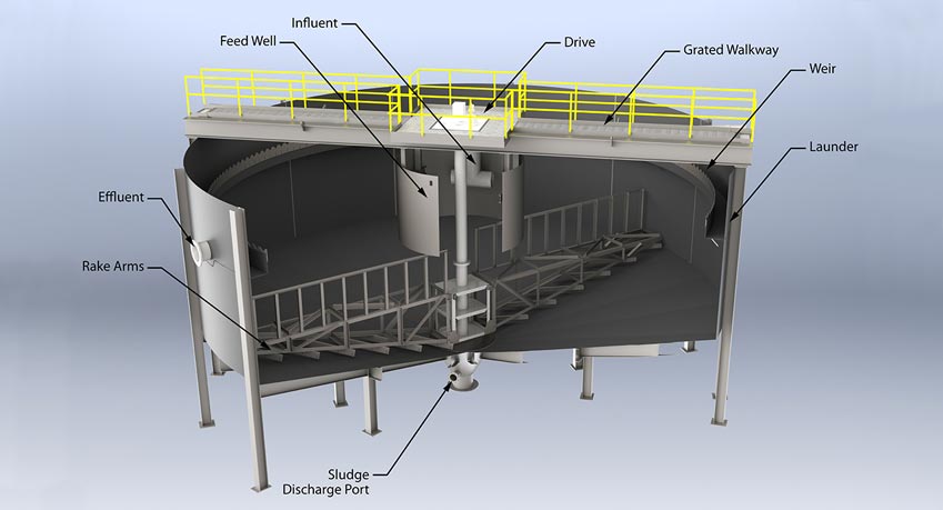
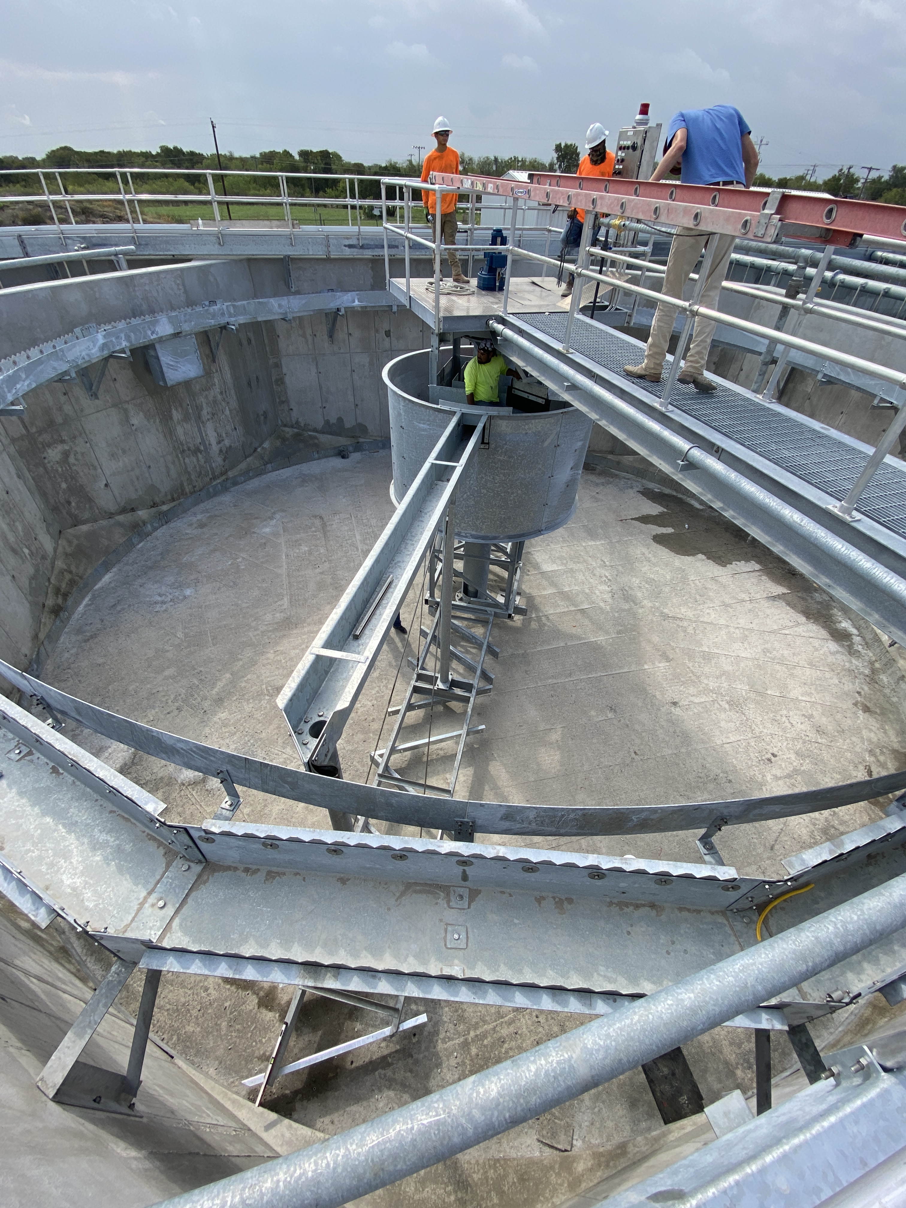
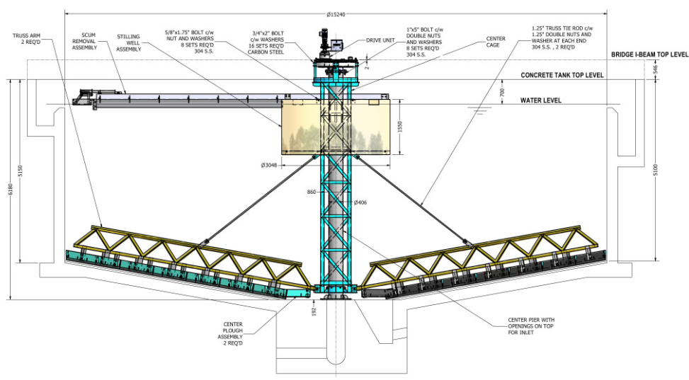
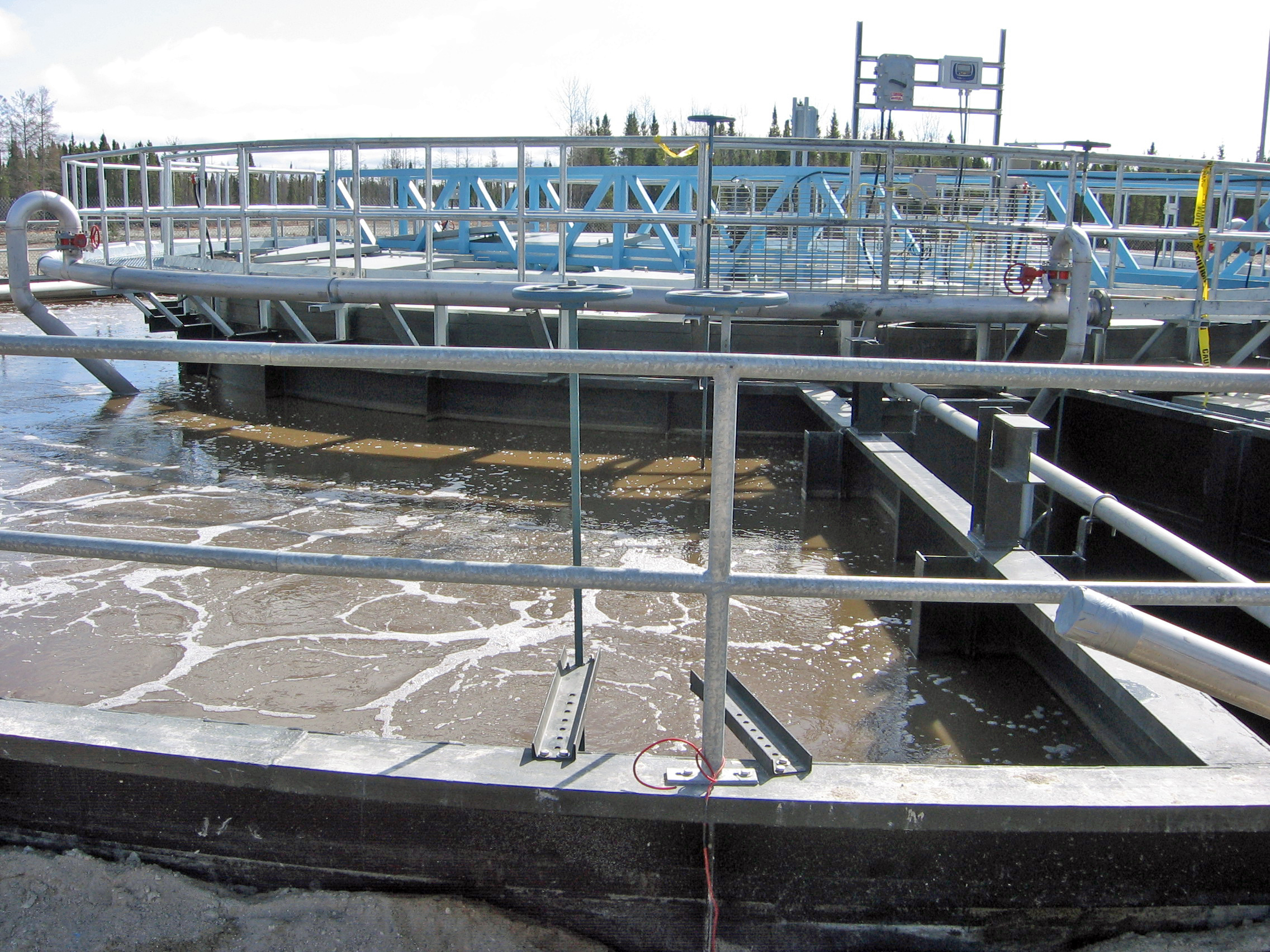
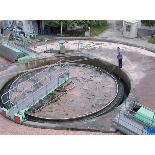
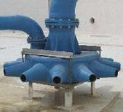
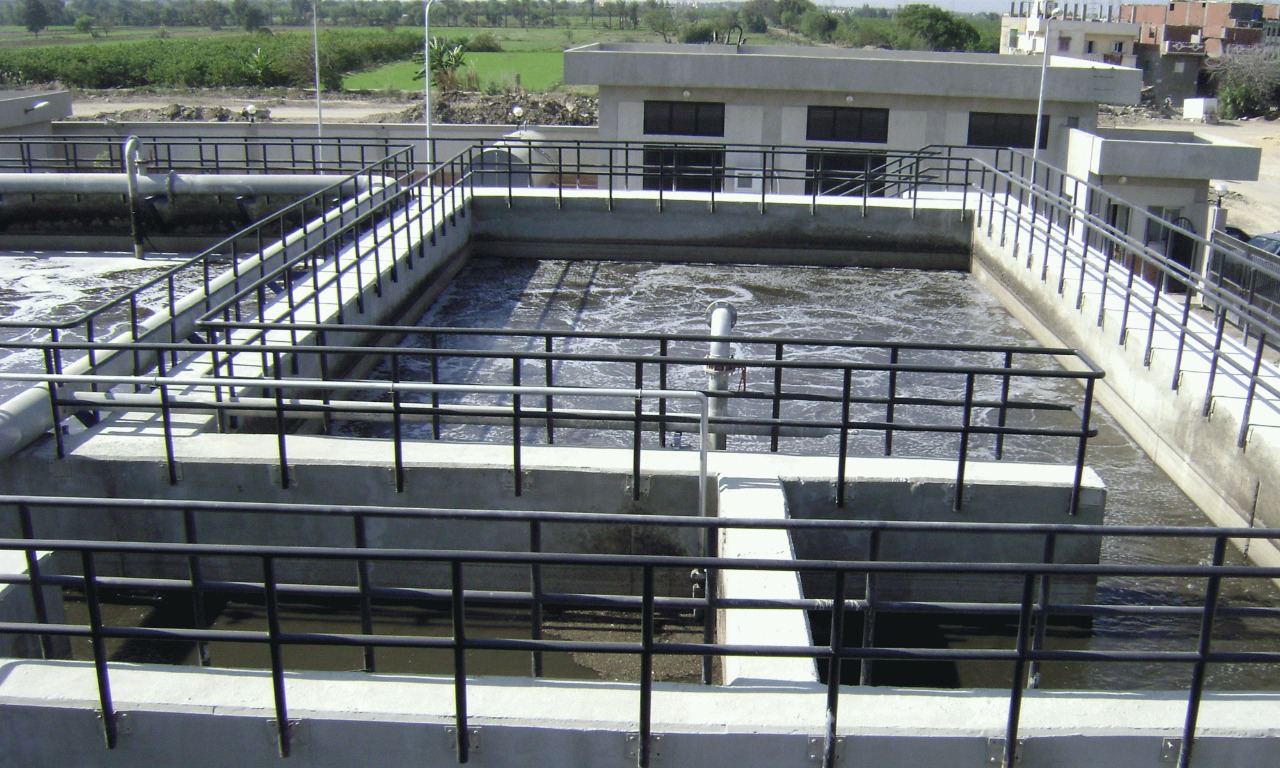
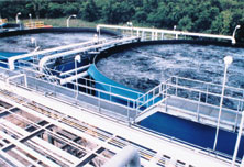
Circular Clarifiers:
Circular clarification technologies designed to treat water or wastewater to remove particles and reduce total suspended solids (TSS) to low levels.
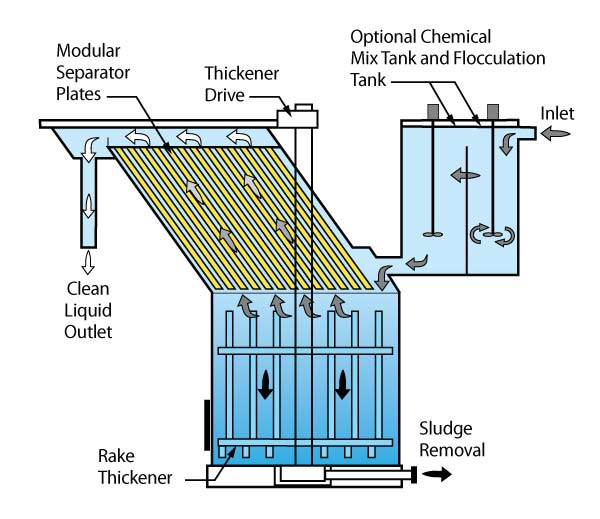
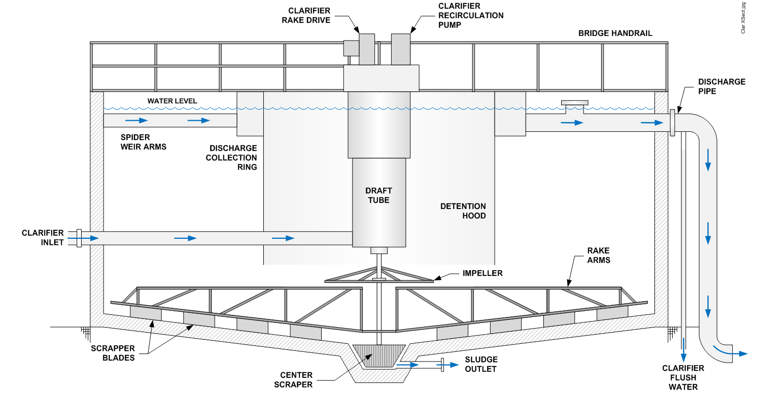
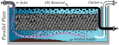
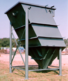
Clarifiers – Plate:
To meet your liquids/ solids separation needs, we supply a full range of separator devices, such as skimmers, decanters, and other ancillary equipment.
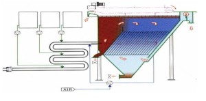
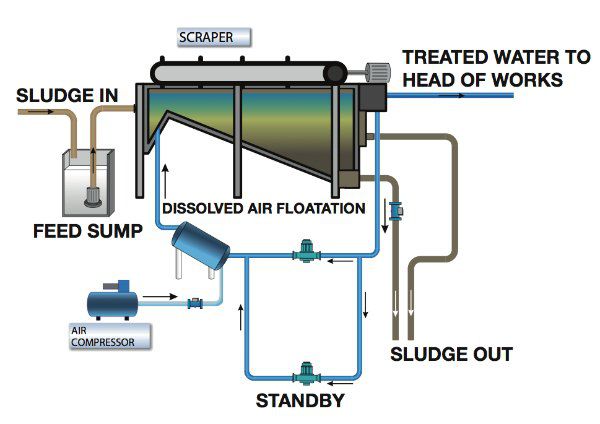
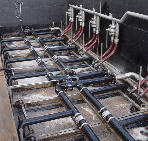
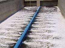
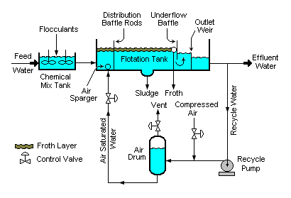
Flotation Equipment and Systems – (DAF, IAF):
Dissolved air flotation and induced air flotation are two separation methods used to separate liquid from solids.

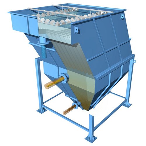
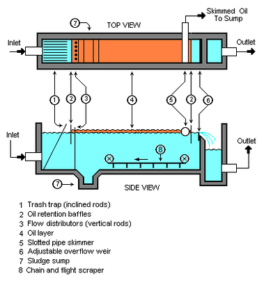
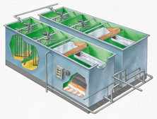
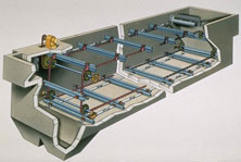
Rectangular Clarification Technologies:
Rectangular clarification is a separation process commonly used in very large or confined municipal and industrial spaces to remove contaminants from liquids, because it makes the most out of the available space.
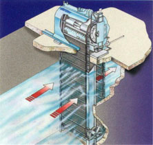
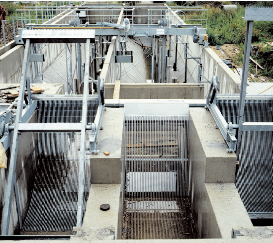
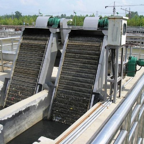
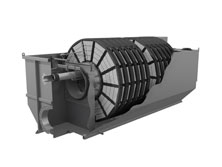
Traveling Water Screens:
debris removal for power plants, municipal drinking water intakes and other screening applications.
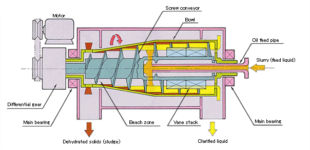
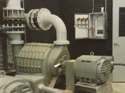
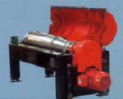
Decanter Centrifuge, Decanters, Centrifuges Decanter Decanter Centrifuge range provides an effective, low-maintenance solution to continuous liquid clarifying and / or solids dewatering with advanced process and mechanical performance
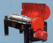
features.
Decanter Centrifuge Advantages
The hydraulic scroll drive also provides significant processing advantages:
Automatically maintains constant torque load and pressure on the scroll during operation
Automatically adjusts and compensates for changes in the feed material
Provides three easy to use settings controlling
Scroll pressure
Scroll differential speed
Scroll speed boost
Scroll can be turned when the bowl is stopped
Scrolls can be operated in a “leading” or “lagging” condition
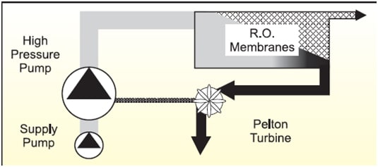
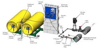
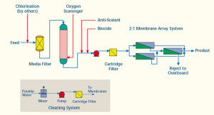
Sulfate Separation system controls scale formation:
Where seawater contains sulfate and formation water contains barium and strontium, the result is the potential for significant barium and strontium sulfate scaling and possible reservoir souring. Scale deposits are a common problem in water injection, the type and severity of scaling varying between fields.
In the 1980s Dow Chemical Company developed these membranes to reject selectively sulfate ions in seawater while allowing sodium and chloride ions to pass through. Since then in addition to minimizing the potential for scale formation and associated well workover and squeeze treatment costs, the reduced sulfate levels are so low that the potential for reservoir scouring can be reduced. Today the third generation membranes are in use on offshore platforms which have a 25% increase in membrane surface area, allowing increased throughputs and thus decreasing space and weight requirements of the sulfate removal facility on an oil platform.
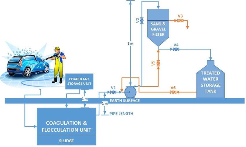
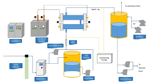
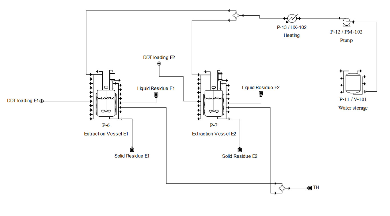
General Flow Diagram,
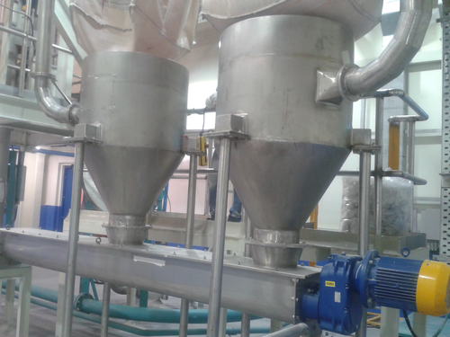
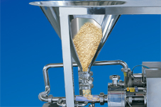
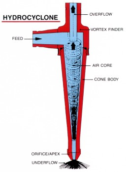
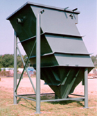
Hydrocyclones for Potato Starch Recovery:
small diameter hydrocyclones are being used at potato crisp and chip manufacturing plants to recover starch solids from the plant effluent water. Recoveries of around 80% starch are being achieved. More than 90% of the process water can be reclaimed. The use of Hydrocyclones instead of settling tanks and centrifuges reduces the separation time substantially. Washing and thickening duties also utilize these hydrocyclones.
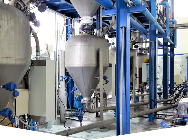
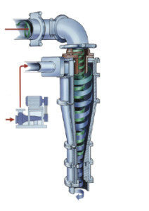 Hydrocyclones for Corn Starch Treatment:
The corn starch wet milling industry uses 600mm ( 24″ ) and 200mm (8″) cyclones for stone and grit removal; 150mm (6″) cyclones for germ separation. 12mm cyclones are used extensively in starch washing circuits where their high capacity and exceptional gluten removal efficiency makes them an ideal choice. 10 mm cyclones are used in starch recovery and thickening duties.
LIQUID / LIQUID Seperation:
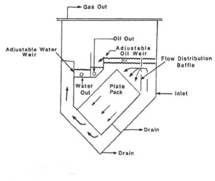
Liquid / Liquid Coalescer Packs:
The coalescer packs are placed in the liquid

section of horizontal separators in order to assist with effective separation of water & oil.
Two basic fluid dynamic principles, as well as innovative physical dimensioning, govern the operation of separating liquid phases. Laminar, stable flow maintained between the corrugated plates, allows conventional settling (i.e. in accordance with Stoke’s Law) to be much more efficient. Decreasing the travel distance to an interface (and subsequent removal) reduces the retention time required to effectively treat a given volume of water. This can improve existing separator performance or decrease the vessel size in new designs.
Desalter / Electrostatic Treater Internals:
Electrostatic treaters are utilized to remove water from oil to high efficiencies (below 1.0% BS&W). Electrostatic separators additionally act as desalters as they remove water that contains salt. Some times desalters consist of a upstream mixing device in which fresh water is used to wash the crude or desalters can have one or two satge desalters in order to minimize dilution water requirements. AMR Process Inc. offers various designs of electrostatic treaters and desalters and provide the process internals, proprietary transformer hook up electrical materials together with a process guarantee.
Electrostatic oil dehydrator configurations:
Advanced Treater – This is a horizontal vessel with vertical oil flow through electrostatic grids which effective dehydrate oil.
Desalter – This is an electrostatic oil dehydrator that additionally reduces the salt content of the export oil, utilizing dilution water.
Heater Treater – A fire tube is included in the electrostatic vessel for heating of bulk fluid, with initial stage separation of water/oil/gas, before passing through an electrostatic grid.
Electro-Mechanical Treater – Combines the high efficiency mechanical separation of a coalecser plate pack with the high efficiency separation of an electrostatic grid. This design can be problematic if used with waxy oils and solid loadings but is advantageous at breaking problematic emulsions.
Types of electrostatic fields:
AC-Plus – Three phase AC converted to single phase AC high voltage field. Excellent for breaking emulsions, low API oils and high inlet water contents.
AC-Direct – Three phase AC converted to DC high voltage field. Improved oil throughputs providing smaller vessel sizing.
AC-Tri – “Scott” connection, three phase hook AC up converted to two phase AC high voltage field. Excellent at balancing loads on electrical generation equipment.
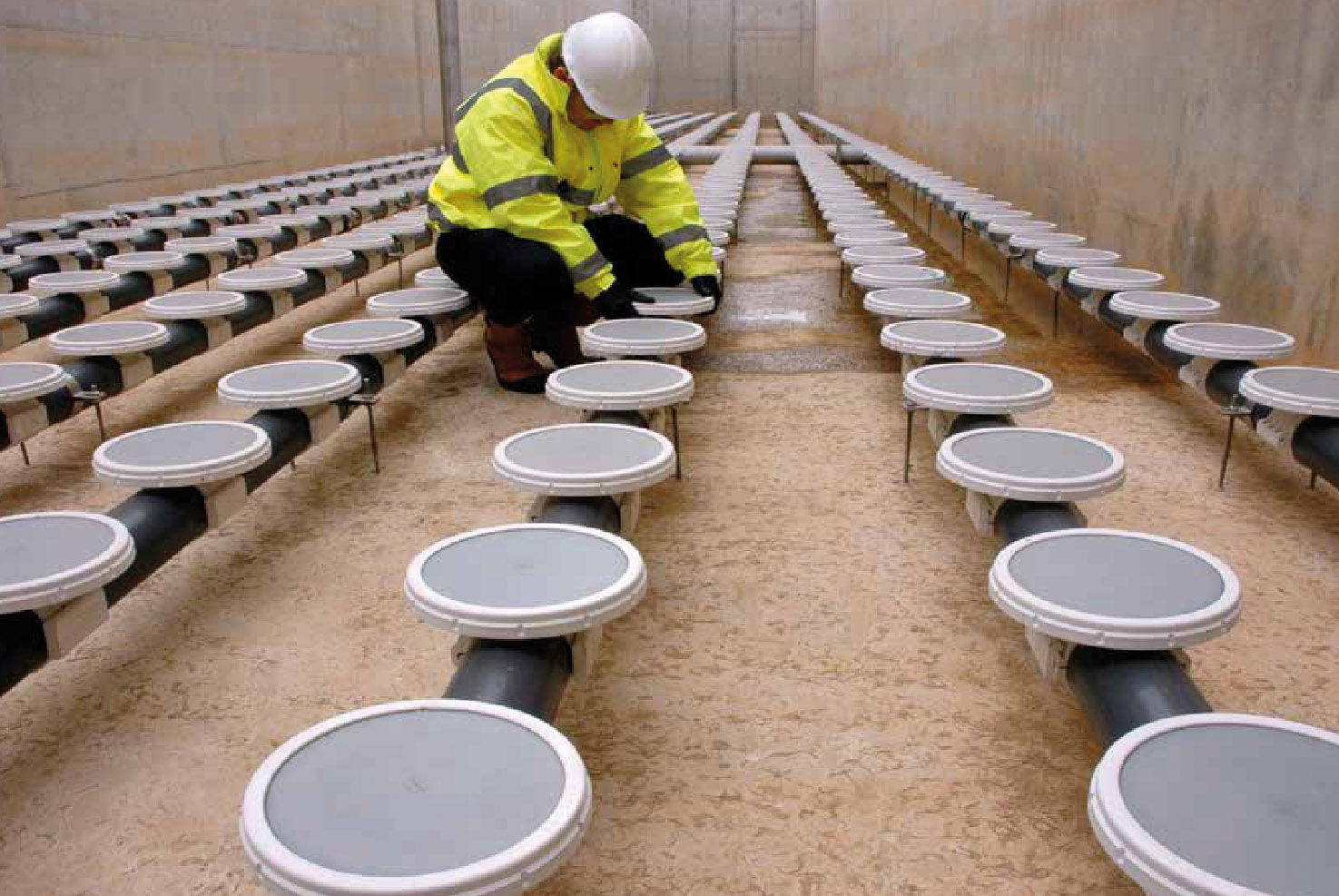
Liquid Gas Sepeartion
Cyclonic Demisters
Another method of removing liquid particles from the gas stream in a separator utilizes centrifugal force. The gas stream enters a multi-cyclone or cyclonic bundle that spins the gas, forcing the liquid to the cyclone wall. The liquid drains out of the cyclone at a low pressure recycle opening, whilst the gas turns around upon itself and flows free of liquid out the bottom of the cyclone tube.
The cyclonic demister provides more efficient removal of liquid particles than the mesh pad or vane pack demister at steady state flows, and also provides smaller diameter vessels. This makes the cyclonic demister very cost competitive, especially for high pressure applications. The cyclone demister also effectively removes solids. The cyclone demister does however have a limited turndown to around 25% of design flow, as the performance is dependent on the centrifugal force that is reduced as gas flow decreases.
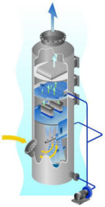
Plate Scrubbers:
Plate scrubbers are a highly efficient means of particulate removal, absorption of contaminants and gas cooling. In this type of scrubber (see photo) the gas passes upwards through a number of small holes in one or more plates. Liquor enters on the top plate, flows across it and through a down-comer to the plate below. Intimate gas liquid contact is obtained as the gas bubbles through the liquid on the plate.
In the target plate design a “target baffle” is located over each hole in the plate. As the gas passes through the perforations the dust particles impinge on the “targets” and they are collected by the liquor. For increased dust removal performance a venturi scrubber can be incorporated into a tray design in the form of a venturi slot plate.
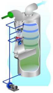
Venturi Scrubbers:
Venturi scrubbers are an effective means of removing sub micron particulates. The contaminated gas is accelerated in the converging section before entering the throat (see photo). Scrubbing liquor enters around the top of the converging section and completely flushes the wall. In addition, liquor enters through a spray to fill the throat with droplets.
In the venturi throat, the high velocity gas atomizes the liquid droplets with trap the solid particles. The scrubbed gas and liquid droplets leave the venturi throat and pass through the diverging section where further agglomeration takes place to produce larger droplets. The liquor droplets are then separated from the gas stream in a cyclonic entrainment separator.
To ensure high scrubbing efficiencies, even with varying gas flows, the throat can be made adjustable, thus maintaining the required scrubber pressure drop, even at reduced throughputs.
The liquor from the separator is recycled via pumps to the venturi scrubber with a small bleed being discharged to control the build up of solids in the circulating liquor.
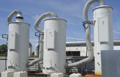
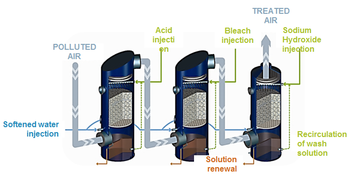
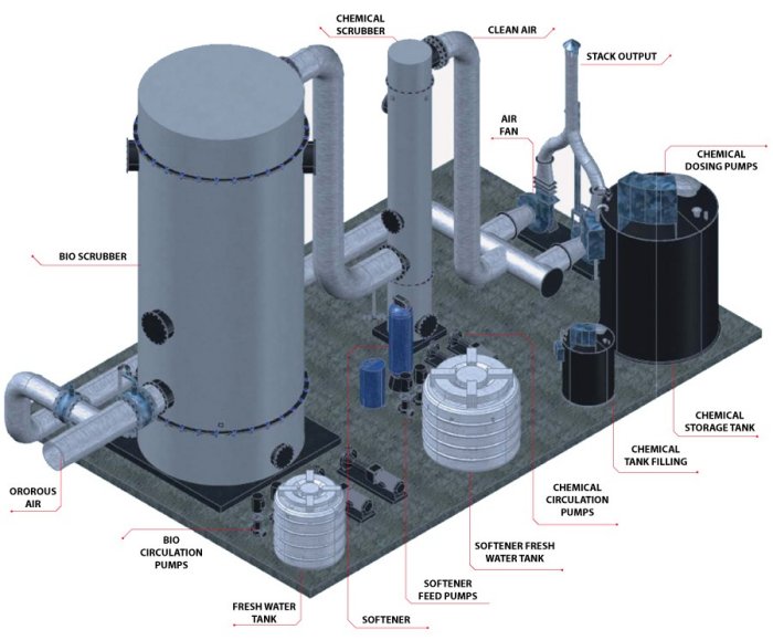
Packed Towers:
Wetted packed towers are the simplest and most commonly used approaches to gas scrubbing. The principle of this type of scrubber is to remove contaminants from the gas stream by passing the stream through a packed structure which provides a large wetted surface area to induce intimate contact between the gas and the scrubbing liquor. the contaminant is absorbed into or reacted with the scrubbing liquor.
The packing of the tower is normally a proprietary loose fill random packing designed to encourage dispersion of the liquid flow without tracking, to provide maximum contact area for the ‘mass transfer’ interaction and to offer minimal back pressure to the gas flow. The reactivity between the contaminant and the scrubbing liquor influences the system designer’s determination of gas and liquor flow and the height and diameter of the packed bed.
A demister is fitted at the top of the tower to prevent entrainment of droplets of the scrubbing liquor into the extraction system or stack.
Wetted packed towers can be designed for very high efficiencies with relatively low capital and running costs. The low pressure drop associated with packed bed scrubbers permits the use of smaller more economical fans. Although efficiency may be affected, a packed tower will usually function when gas or liquor flows vary from its original design parameters.
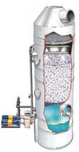
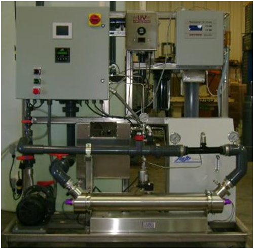
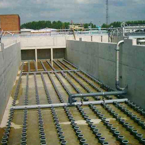
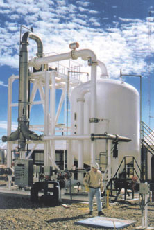
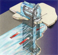
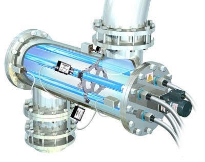
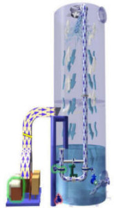
Air Strippers:
Dissolved gases such as hydrocarbons ( VOC’s), carbon dioxide, ammonia and hydrogen sulfide can be removed from water by stripping (desorbing) by contacting the water with ambient air in a packed column. The water to be treated enters the top of a packed tower and is distributed over the top of a packed bed and flows down through the packing. Fans blow ambient air into the base of the tower and this flows up through the packing where it contacts the water stripping out the VOC contaminants. The air containing the stripped VOC’s passes through a demister to remove water droplets and is vented to atmosphere. The stripped water collects in the base of the stripping tower from where it is discharged. The efficiency of the VOC removal depends on the vapor pressure of the specific VOC compounds, the temperature of operation and the packed height of the tower. The materials of construction of the stripping towers would be either stainless steel or glass reinforced polypropylene. The internals would be manufactured from polypropylene.
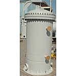
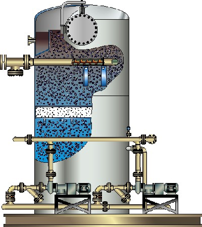
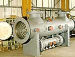
Gas / liquid vertical separator filter:
The Plenty Vertical Filter Separator will remove 100% of all droplets 8-10 microns and larger and 99.5% of all droplets ½-8 microns in size. It will also remove 100% of all solid particles, 3 microns and larger 99% of all particles ½-3 microns in size. These operating efficiencies apply over the entire flow range from maximum design down to virtually zero flow. The first stage of the filter separator consists of a number of glass fibre coalescer /filter elements through which the wet gas passes. The small liquid drops carried in the gas stream are trapped within the glass fibres of the element and coalesce to form drops 100 to 200 times larger than the original size. These drops pass through the element wall and are carried forward by the gas stream to the second stage vane type separator. The second stage consists of a vane type impingement separator, which operates exactly as described for vane separator.
Its maintaining the required scrubber pressure drop, even at reduced throughputs.
The liquor from the separator is recycled via pumps to with a small bleed being discharged to control the buildup of liquor.